Completeness Design of Connection and Immersion in Non-Sequential Optical Simulation Systems and Case Demonstrations
1. Introduction
While simulating optical systems using optical software, besides the implementation of key algorithm prototypes as a functional guarantee, numerous other software engineering challenges must be addressed to faithfully reproduce real-world scenarios. In non-sequential ray tracing, particular attention must be paid to the accurate configuration of connected and immersed interfaces between geometrical elements.
Sequential ray tracing primarily focuses on lens system design, where the main optical effects—refraction and reflection—can be adequately described by the refractive index and curvature of surfaces. The parameters of each component in the optical system, such as curvature, thickness, material, radius, and position, are inputted and modified through a structured and detailed lens data editor. This method facilitates the tracking and updating of a large number of parameters. By defining materials at specific surfaces, it naturally delineates the cementing of lenses and material transitions during the tracing process.
Conversely, non-sequential ray tracing must account for a broader range of optical phenomena, including complex scattering and surface roughness, necessitating more detailed interface property settings. Consequently, considerations and treatments for environmental materials and boundary properties become significantly more intricate. Efficiently and accurately identifying materials and boundaries, and performing numerical calculations and processing at the correct material and boundary interfaces, is a core challenge that persists throughout the non-sequential ray tracing process.
In ray tracing, the direction of a ray changes due to two factors: one, when it encounters a boundary between different media, leading to reflection, refraction, or scattering; and two, when it strikes volume-scattering particles within the material. Regardless of the cause, it is crucial for the ray to always know its current environmental material and the optical properties of any boundary it encounters at any given moment. This capability of continuously updating the state of the ray is essential for achieving high-quality optical simulations.
2. How to Design Inspection Logic?
Users may not understand why a question that seems so obvious can be a challenge in software engineering. The following example is used to simply illustrate the considerations involved in the logic design process:
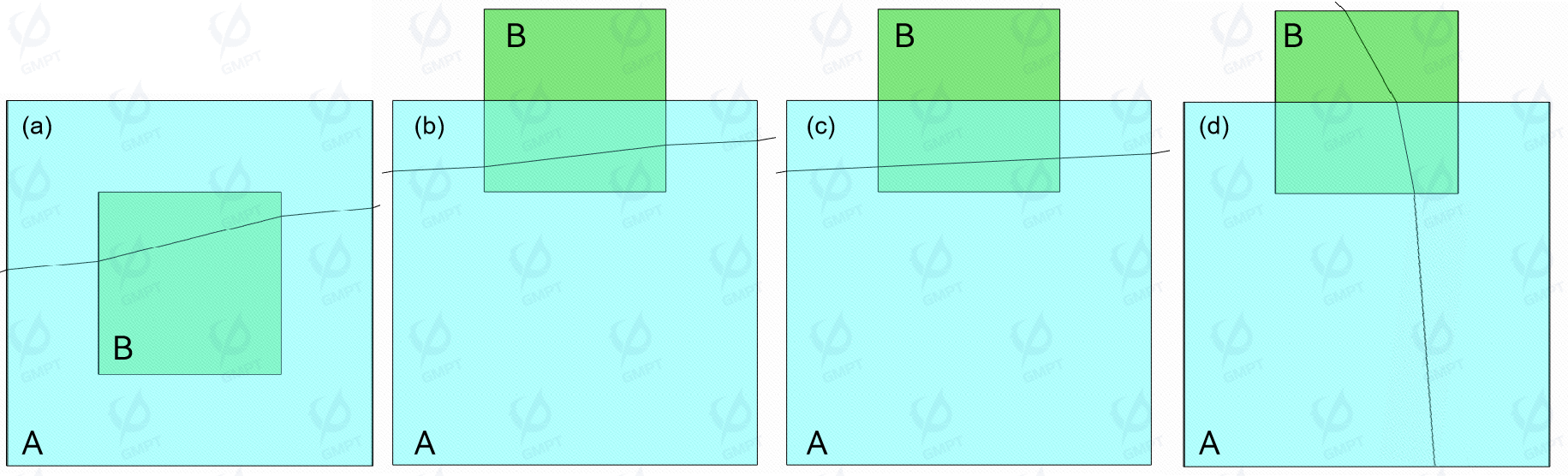
As shown in Figure 1(a), in the scenario where small geometry B is completely immersed within larger geometry A, the algorithm logic can be designed as follows: when a ray intersects with a surface, identify the materials on both sides of the surface and perform calculations based on Snell's law. Now, let us extrapolate this scenario; as illustrated in Figure 1(b), when small geometry B is partially immersed in large geometry A, the behavior of the rays remains consistent with the aforementioned logic. However, if it is desired that the overlapping part of A and B is recognized as A, the rays should ignore B, as shown in Figure 1(c). In this case, the algorithm must be additionally designed to support such scenarios.
Furthermore, as depicted in Figure 1(d), when a ray traverses the scene from top to bottom, refraction occurs at both the lower surface of B and the upper surface of A. This logical outcome is incorrect under physical reality.
3. Which are the possible scenarios?
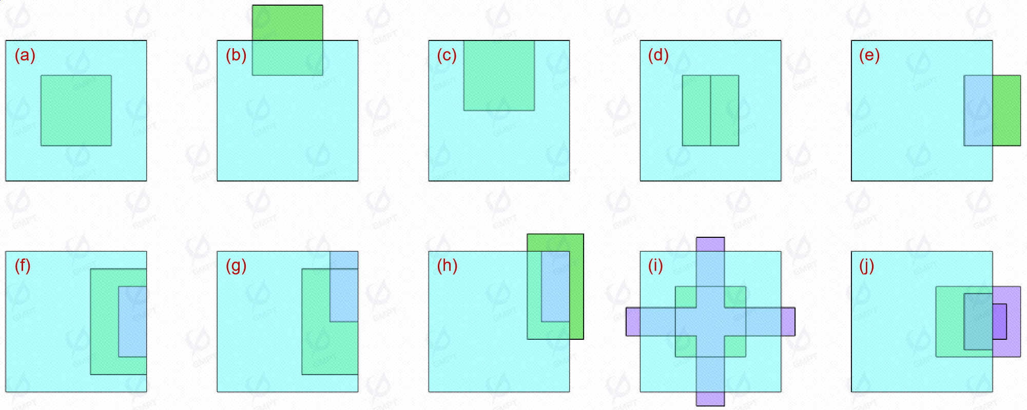
The above is just a simple set of deductions in the verification scheme. In fact, due to the freedom of scene settings in non sequential scenarios, we still need to consider many more complex situations, as shown in Figure [2]:
4. Solution: Connection & Immersion Manager
Figure [2] illustrates several cases involving multiple immersions or overlaps with multiple surfaces. In these varied scenarios, comprehensive setup procedures and rigorous error checking are necessary to ensure scene consistency. For example, it is not feasible for the same two geometries to simultaneously exhibit both connection and immersion, nor should there be any contradictory immersion relationships. To address these challenges, we will consider the last two images as representative of the same scenario and introduce Rayzen software’s approach: utilizing the Connection and Immersion Manager to manage these complex interactions.
4.1 Immersion Manager
The Immersion Manager employs a single criterion for grouping geometries within a scene: any geometries that are "connected" to each other must belong to the same immersion group. Here, "connectivity" is defined similarly to the "connectivity of bounded open intervals" in topology, meaning geometrically that the intersection volume between connected components is non-zero.
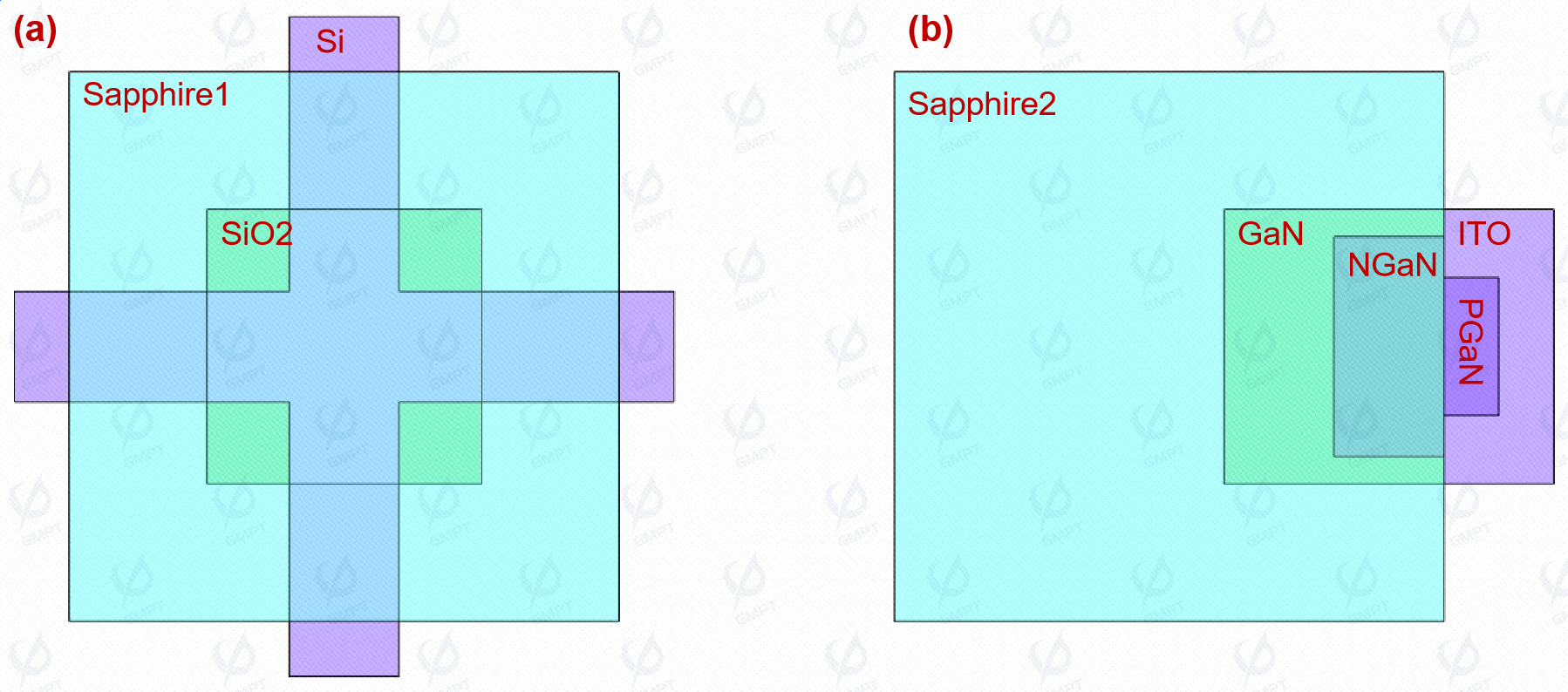
As illustrated in Figure [3], the scene comprises two sets of components: one set includes Si, SiO2, and Sapphire1, while the other encompasses Sapphire2, GaN, NGaN, PGaN, and ITO. Given that the intersection volume between (Sapphire2 GaN NGaN) (PGaN ITO) is zero. it is feasible to divide these into three distinct groups. The rationale for this grouping is based on the independence of the two geometric sets from each other and their interconnectivity within each set. This criterion allows for a swift determination of the immersion relationships.
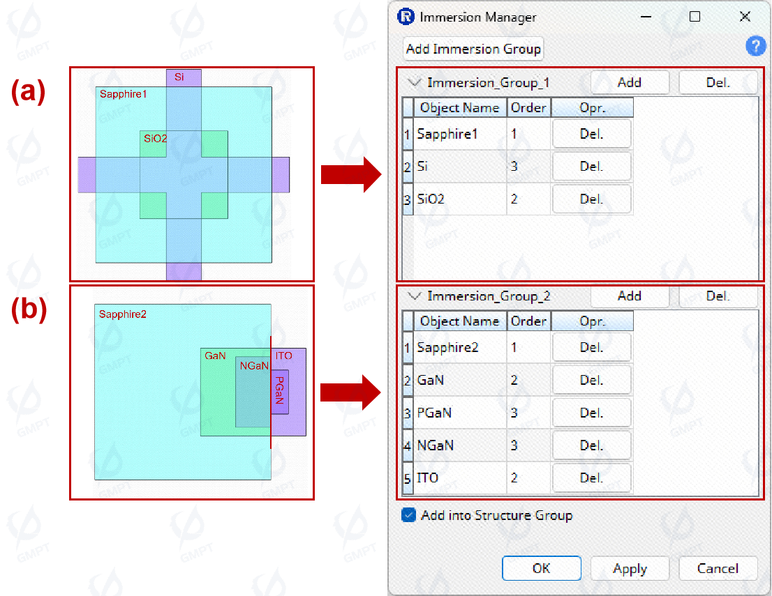
As shown in Figure [4], the minimum priority number assigned to an immersion group is 1, with no upper limit. If there is no actual immersion relationship between geometries, they can be assigned the same or different priority numbers as appropriate.
4.2 Connection Manager
The Connection Manager in Rayzen software identifies and manages the optical properties and material interactions when surfaces overlap. A "connection" is defined as an overlap between two faces in space where, at every point of overlap, the normal vectors of these faces are exactly opposite (with the normal vector of any point on a solid face pointing outward). Overlapping faces with identical normal directions are managed by the Immersion Manager.
In the scene shown in Figure [6], six connection relationships need to be defined between the three faces on the left side (Sapphire2, GaN, NGaN) and the two faces on the right side (PGaN, ITO) of the interface.
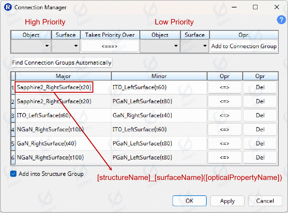
As illustrated in Figure [6], when establishing a connection relationship, the surface on the left side (Major) has a higher priority than the surface on the right side (Minor). You can switch the priority of the surfaces by clicking the Takes Priority Over button. The optical properties used by each surface are indicated in parentheses after the surface names. For instance, t20 denotes an optical property with 20% transmittance and 80% absorbance, while T40, t60, t80, t100, etc., represent various transmittance levels. To create a new connection group, use the Add Connection Group button. When using the Connection Manager, please note the following:
The Connection Manager is active only when the scene contains two or more geometric entities.
If regions or two-dimensional textures are defined on the high-priority surface, the optical properties specified for these regions or textures take precedence. Even if regions or two-dimensional textures are present on the low-priority surface, the optical properties of the high-priority surface will override them.
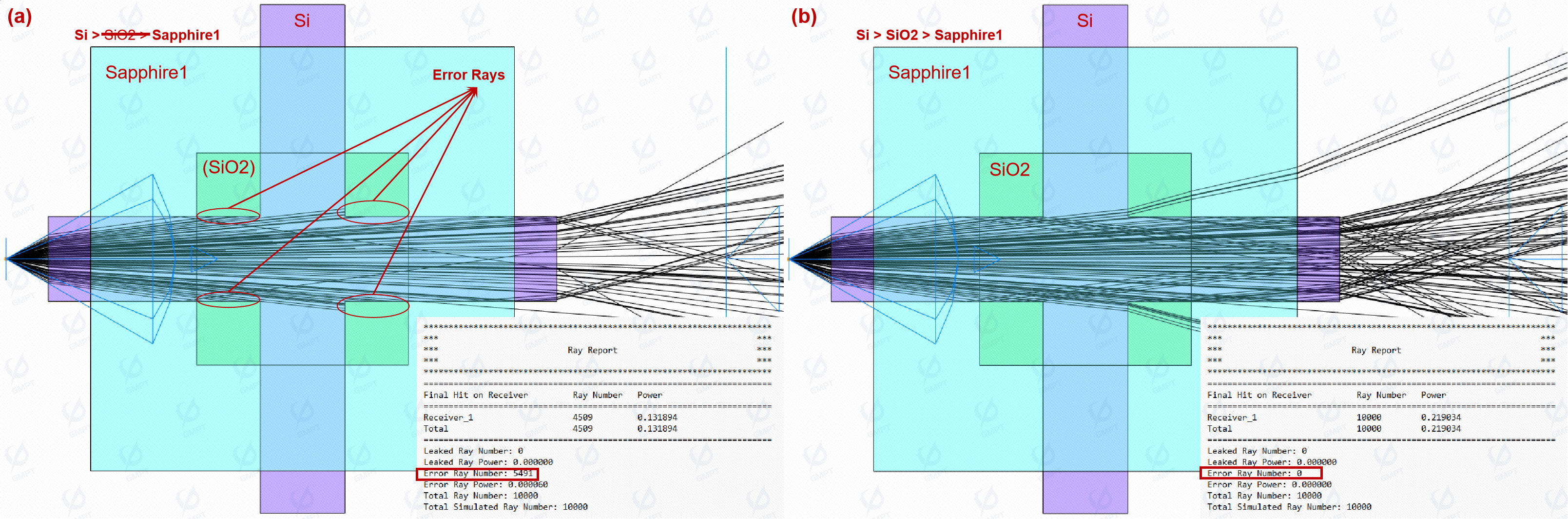
If surfaces of geometric entities in the scene overlap without correctly configured connection relationships, the core tracing calculations may yield unexpected results.
We use the Probe Ray feature in Rayzen software to validate the correctness of connection settings in complex scenes.
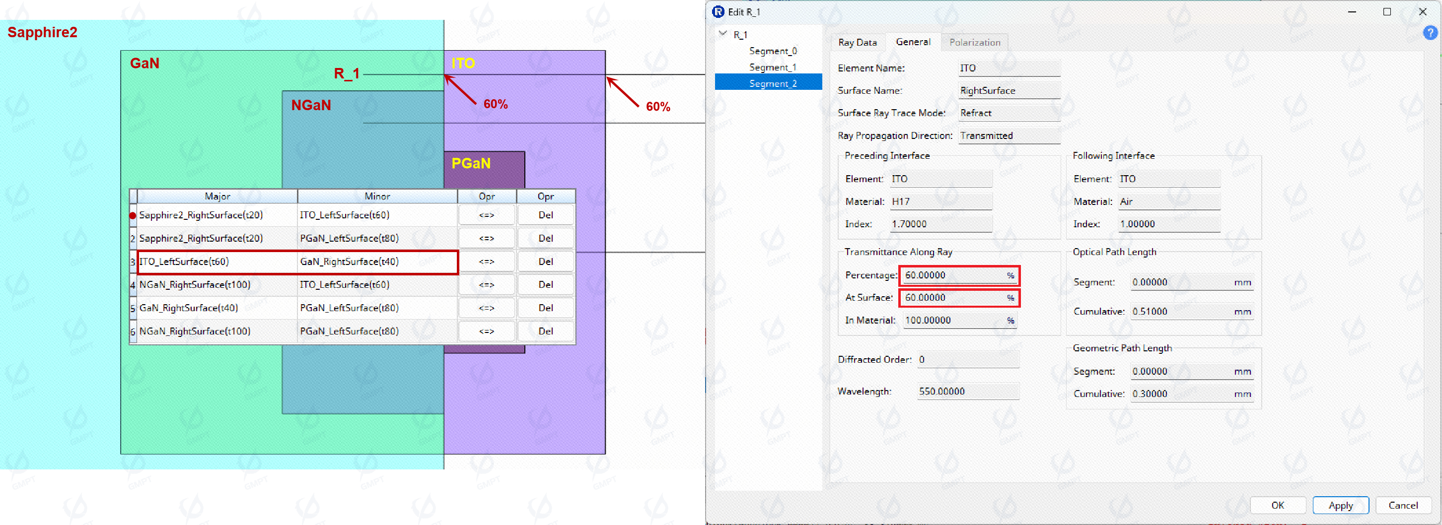
As illustrated in Figure [7], ray R1 traverses an interface with three overlapping surfaces. Because GaN has a higher immersion priority than Sapphire 2, the Sapphire 2 surface is effectively ignored, and only the optical properties of the GaN and ITO surfaces need to be evaluated. In the Connection Manager, the ITO surface is given a higher priority with a transmission setting of 60%. As a result, the final segment of ray R1 passes through 60% transmission property twice.
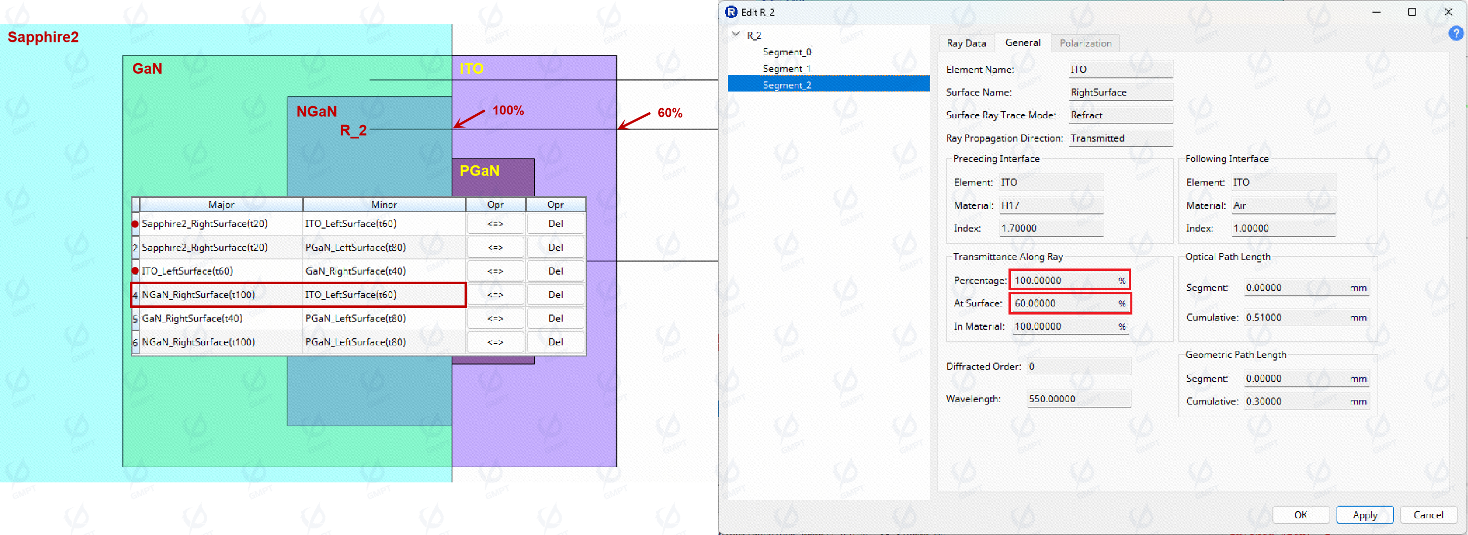
As illustrated in Figure [8], ray R2 traverses an interface where four surfaces overlap. Given that NGaN has a higher immersion priority than Sapphire2 and GaN, the surfaces of Sapphire2 and GaN are effectively screened out. This means only the optical properties of the NGaN and ITO surfaces need to be evaluated. In the Connection Manager, the NGaN surface is given a higher priority with 100% transmission. Therefore, the final segment of ray R2 first experiences 100% transmission through NGaN, followed by 60% transmission through ITO.
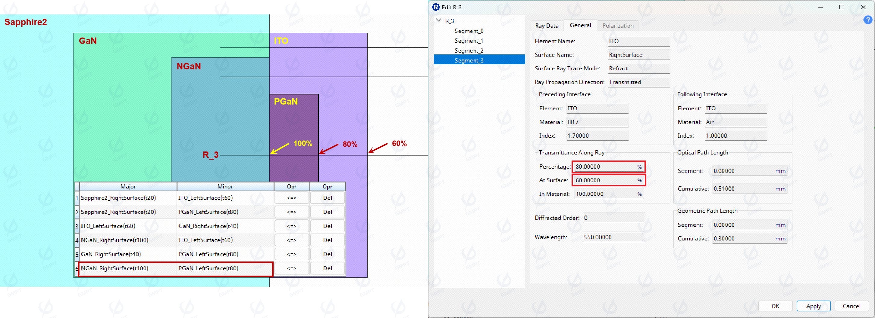
As illustrated in Figure [9], ray R3 traverses an interface where six surfaces overlap. Given that NGaN has a higher immersion priority than Sapphire2 and GaN, the surfaces of Sapphire2 and GaN are effectively screened out; PGaN has a higher immersion priority than ITO, the ITO surface is effectively ignored, and only the optical properties of the NGaN and PGaN surfaces need to be evaluated. In the Connection Manager, the NGaN surface is given a higher priority with 100% transmission. Therefore, the final segment of ray R3 first experiences 100% transmission through NGaN, followed by 80% transmission through PGaN, and end with 60% transmission through ITO.
4.4 Error Checking and User Prompts in Rayzen Software
Rayzen software meticulously evaluates the interdependencies between connection, immersion settings and other modules, providing robust error checking and user prompts to prevent designs that violate physical principles, thereby enhancing software stability. Key features include:
Prevention of Simultaneous Connection and Immersion Settings: The software prohibits configuring two geometries for both connection and immersion simultaneously, as this would be physically inconsistent.
Elimination of Contradictory Connection Settings: It prevents the establishment of two sets of connections that conflict with each other, ensuring adherence to physical reality.
Restriction on Incompatible Surface Selections: When selecting two faces with different shapes for a connection, the software disallows setting a connection to avoid potential modeling failures. Future updates will support automatic lens fitting interaction optimization to further enhance these capabilities.
... ...
These measures ensure that users receive timely feedback and guidance, facilitating accurate and stable optical design simulations while adhering to physical constraints.
4.5 Improvements and Advantages Compared to Similar Software
Traditional optical design software often bypasses the geometric processing challenges associated with connection and immersion relationships by delegating this complex logic to CAD modeling accuracy. While this approach can effectively modularize complex problems, beneficial for software engineering implementation, it also presents several issues in practical applications:
Dependence on CAD Model Quality: The effectiveness of this method largely depends on the quality and accuracy of the CAD model. Errors or insufficient precision in the CAD model can directly impact the results of optical design, especially for complex geometries and fine interface processing.
Lack of Flexibility in Prototype Design: During initial prototype design, handling geometric relationships lacks flexibility. For instance, simulating packaging structures requires first hollowing out the packaging layer based on internal geometry, followed by precise adjustments to ensure interfaces meet preset optical tolerances.
Interface Processing Challenges: Light behavior at interfaces is influenced by both CAD model accuracy and numerical parameter errors, complicating problem identification.
Lighttools software, as a long-standing lighting design software, has a comprehensive approach to handling connection and immersion relationships. Through clear definitions and configurations, it can effectively solve the above-mentioned problems. In contrast, Rayzen has added the following additional support:
- Optimized Immersion Manager Settings: By placing the Immersion Manager above the geometric hierarchy, Rayzen eliminates the need to traverse individual geometries for settings. Instead, it defines priorities globally, simplifying operations and enhancing intuitive understanding.
- Enhanced Connection Manager Functionality: Unlike traditional software where rays only recognize the optical properties of the first surface at the connection point, Rayzen allows users to specify which surface's optical properties should be followed for continued ray tracing.
- Automated Identification of Connection Surfaces: Rayzen supports an automatic search for all surfaces that meet the connection definition, enabling the one-click completion of complex scene connection relationship definitions by pre-specifying optical property priorities.
- Comprehensive Error Checking and User Prompts: Rayzen considers the interrelationships between connection and immersion relationships and other modules, providing effective reminders to users and preventing designs that violate physical reality (as detailed in Section 4.4).
Beyond the mutual constraints of geometric connection and immersion relationships, additional functional linkages must also be considered, such as Boolean operations on geometric bodies, the establishment of surface 3D textures, and the alignment of light source starting points with surfaces. Rayzen has processed this logic effectively and optimized the operations required for complex scenes in recent versions. Below, we present two case studies to further illustrate the usage of the connection and immersion functions in Rayzen.
5.Application Examples
5.1 LED multiple immersion
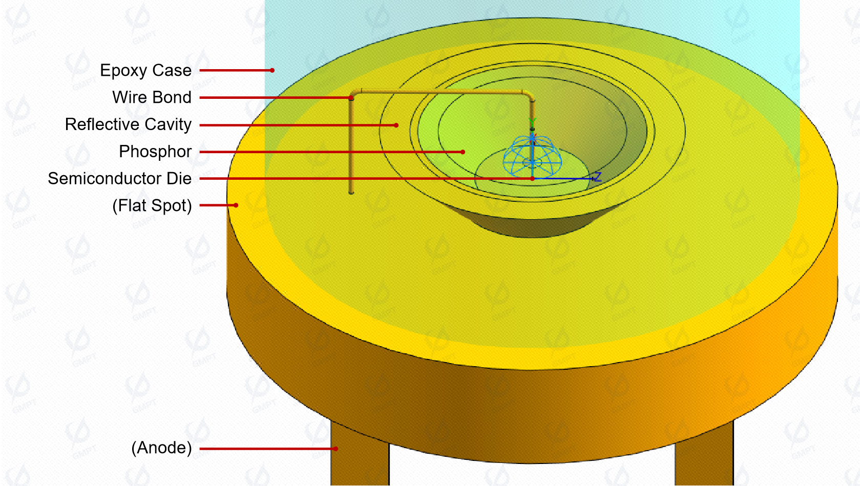
As illustrated in Figure [10], a typical LED model is depicted, where the anode wire penetrates the flat spot and connects to the wire bond. For optical simulation purposes, the circuitry within the flat spot is simplified through Boolean operations, treating the wire bond, flat spot, and anode/cathode as a unified entity. An insulated gap exists between the reflective cavity and the flat spot, while the reflective cavity houses LED chips encapsulated with phosphor powder. The outermost layer consists of an encapsulated epoxy resin lens.
In Rayzen software, the light source automatically recognizes environmental materials without requiring additional user settings. However, it is not advisable to completely overlap the surface of the light source with other geometric entities. If such an arrangement is necessary, we recommend using the "On Object" option for surface light sources.
Light emanates from the light source, traverses the phosphor material, undergoing absorption, conversion, and excitation before being emitted into the epoxy resin interior. During this process, light may encounter the wire bond and undergo reflection, subsequently propagating to the external environment through the packaging. It is evident that the material priority hierarchy is as follows: wire bond/reflector cavity/flat spot > phosphor > epoxy case, comprising three distinct layers of material priority.
There are two primary methods for modeling the LED structure:
- Define Immersion relationship in Immersion Manager Set the geometric boundary of the phosphor material slightly larger than the reflective cavity. This approach requires adding four geometric entities—the wire bond and flat spot, reflective cavity, phosphor powder, and epoxy case—to the immersion relationship manager, specifying their priorities.

Since there is no actual overlap between the wire bond and reflector cavity, they can share the same or different priority numbers. The minimum priority number is 1, with no upper limit. At least three layers of priority need to be defined, ensuring that [wire bond and flat spot, reflector cavity] > phosphor > epoxy case to achieve correct settings.
- Take Connection Relationship Into Consideration Adjust the geometric dimensions of the phosphor to completely overlap with the inner surface of the reflective cavity. Attention must be paid to the rationality of the linkage between connection and immersion settings.
Given the surface connection relationship between the phosphor and the reflective cavity, define the connection relationship between the side of the phosphor geometry and the inner wall of the reflective cavity, as well as the bottom of the phosphor geometry and the lower inner wall of the reflective cavity. Since the expected light behavior at this interface is reflection, select the inner wall of the reflective cavity as the Major Surface.
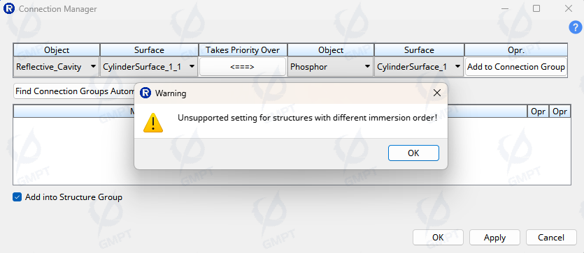
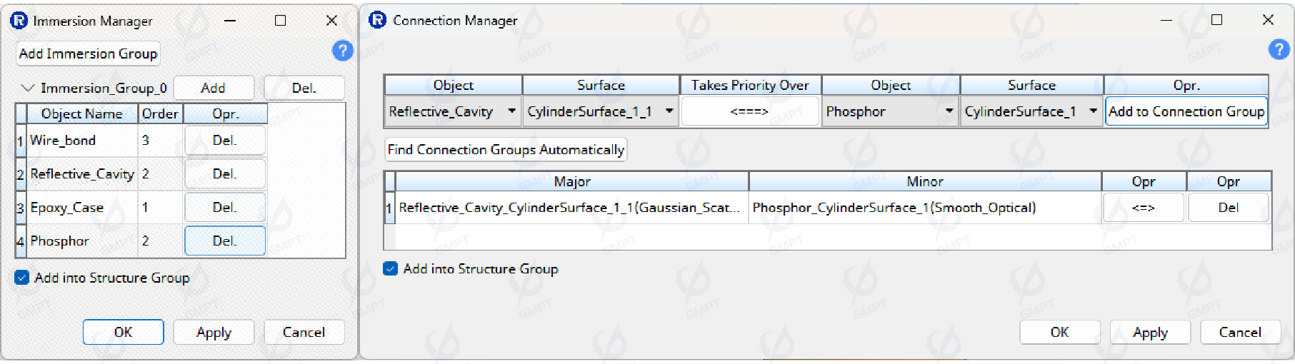
An unexpected conflict occurred (Figure [12]), indicating that if there is an immersion relationship between geometric entities, a simultaneous connection relationship should not exist physically. The software enforces strict adherence to these logical constraints, aiding users in identifying unreasonable or erroneous settings early in the design phase. To establish a valid connection relationship, the phosphor and reflective cavity should be set to the same immersion level (Figure [13]).
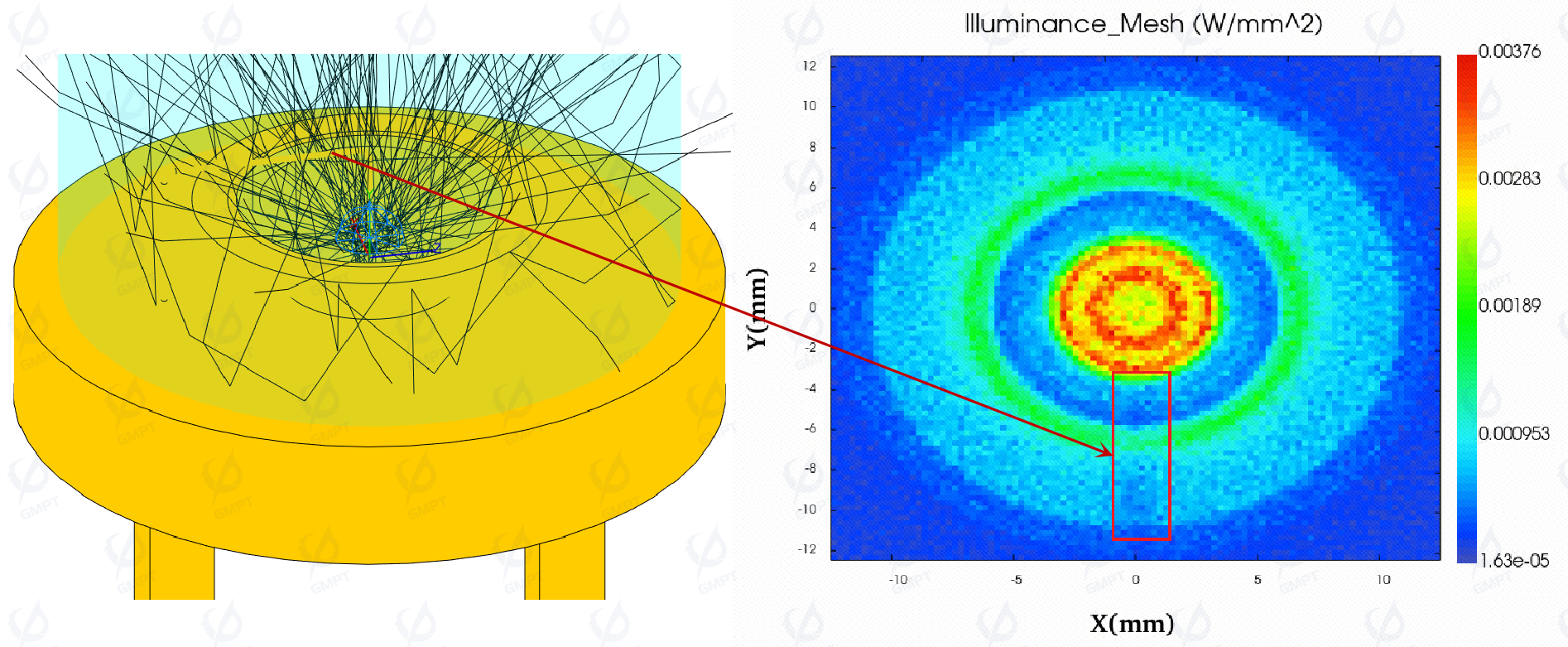
As shown in Figure [14], after correctly configuring the connection and immersion relationships, Rayzen software completed the optical simulation of the LED packaging structure. Ray tracing accurately identified the obstruction and scattering effects of the wire bond on light, resulting in dark spots on the illumination results of the receiver.
5.2 LED Array
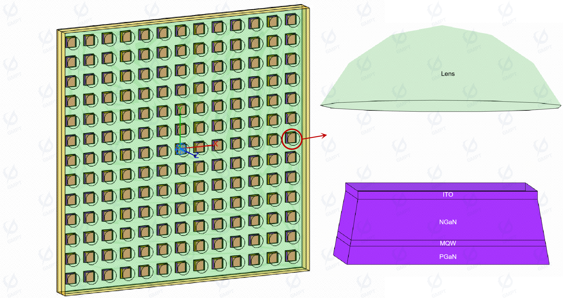
As depicted in Figure [15], a packaged array of Micro LED chips is presented, where each unit comprises the quantum well (MQW), substrate, electrode, and upper lens. The MQW is simplified as a luminescent layer, with its emission distribution characterized by fitted coating data obtained through photometric measurements. The relevant structures are modeled using professional CAD software and subsequently imported into Rayzen for simulation. In this scenario, immersion relationships are not applicable for defining the overlapping interactions between components. Instead, it is essential to meticulously check and set the connection of all overlapping surfaces and determine the optical properties at each interface.
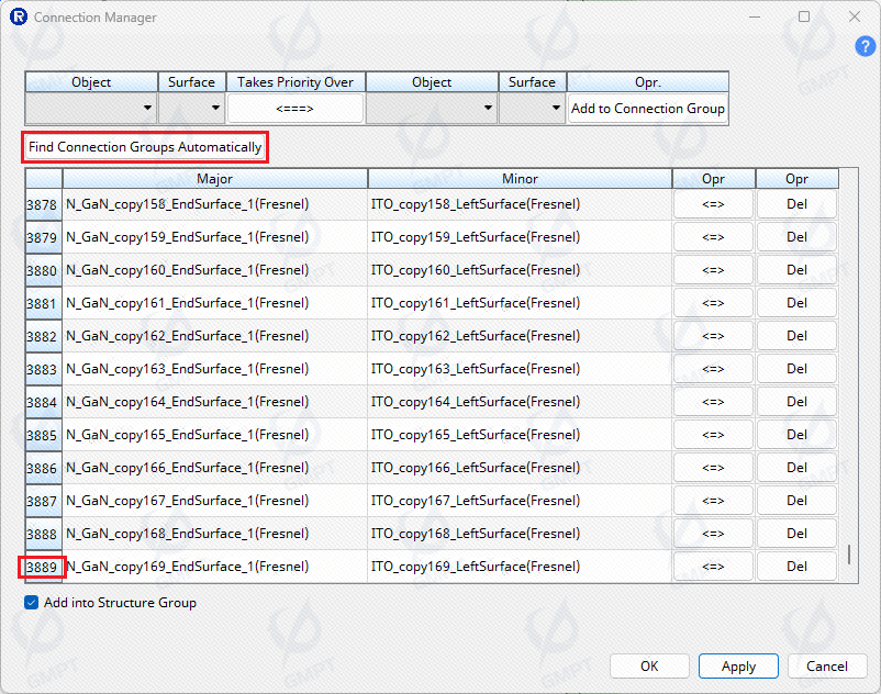
For a single unit, there are 23 pairs of connection relationships that need to be defined. Given that there are 169 units in the scene, this results in a total of 3,887 sets of connection relationships requiring configuration.
In complex optical systems, while millions of surfaces may exist, the number of distinct optical properties typically does not exceed a dozen. Rayzen software supports an automatic search for all connection surfaces that meet the connection definition criteria. By pre-specifying the priority of optical properties, the connection relationship definitions for complex scenes can be completed with a single click, significantly streamlining the process (Figure [16]).
6. Summary
This paper introduces the comprehensive design of connection immersion in Rayzen software, presenting relevant application cases. It elucidates why a completeness design for connection immersion is necessary, starting from simple scenarios and progressively demonstrating the diversity of connection immersion situations and the complexity of their corresponding processing logic. The solution provided by Rayzen involves the use of an connection Immersion Manager, which facilitates the adaptation to complex scenarios and ensures robust detection and prompts for incorrect settings. Practical examples illustrate how this solution adapts to intricate environments and enhances user interaction.
Furthermore, the paper compares Rayzen's approach with similar software to highlight its improvements and advantages in handling complex scenarios—from ensuring physical accuracy to enhancing interactive experience. Through specific application cases, the paper demonstrates the completeness design and application direction of connection immersion within the software. As optical simulation and design applications become increasingly sophisticated, we remain committed to tracking industry developments, providing support for emerging applications, and continuously improving the user experience.