Fundamental Optical Components (Lens)
GMPT, October 2024
1. Application Background
A lens is an optical component made from a transparent substance (typically glass), with at least one surface being part of a sphere, and functions by refracting light. Based on the shape of its surface, lenses can generally be categorized into types like biconvex, plano-convex, biconcave, plano-concave, and spherical lenses. Lens imaging is a common optical imaging technique with applications across various fields:
- Display Technology: Lenses in cameras focus and adjust light to capture clear images. Projection systems, magnifiers, telescopes, and VR headsets also rely on lens imaging principles for an enhanced visual experience.
- Medical Diagnosis and Surgery: Convex lenses are used for vision correction in ophthalmology and for magnifying internal organs, enhancing surgical feasibility.
- Fiber Optic Communication: Lens imaging technology focuses beams precisely into optical fibers for transmission, with lens design and optimization being closely related to communication speed and quality.
- Optical Sensing and Image Processing: Camera lenses capture images for processing and analysis based on lens imaging principles.
In optical design, focusing light with a single lens can lead to chromatic aberration, which cannot be eliminated. By combining convex and concave lenses made from different materials, chromatic aberration at selected wavelengths can be corrected, improving image quality. The design of achromatic lenses, simulated with non-sequential optical software, is especially crucial for imaging systems. Achromatic lenses offer advantages like:
- Dispersion Correction: Achromatic lenses effectively correct chromatic aberrations, improving color accuracy.
- Customizable Design: Achromatic lenses can be tailored for specific applications, enabling complex optical functionalities.
- System Performance Improvement: High surface flatness reduces scatter and distortion, enhancing resolution and image quality.
For larger aperture lenses, the thickness and volume of traditional lenses increase significantly. The Fresnel lens, invented in 1822 by physicist Augustin-Jean Fresnel, offers shorter focal lengths, reduced weight, and volume. Fresnel lenses were initially applied to lighthouse searchlights and are structured by segmenting a continuous curved surface into discrete, concentric sections, drastically reducing thickness but at a cost to imaging quality, limiting their precision in imaging devices. Today, Fresnel lenses are widely used in projection displays, solar concentrators, and optical communications:
- Projection Displays: In projectors, Fresnel lenses collimate and focus light, enhancing edge brightness and uniformity.
- Solar Concentrators: Fresnel lenses focus sunlight from a larger area onto a smaller receiver, reducing solar cell area and saving costs.
- Optical Communication: Used for fiber connection and signal modulation, Fresnel lenses improve performance and efficiency in optical systems.
Fresnel lenses are widely used in automotive headlights, directing light from concave mirrors downward, illuminating the road without glaring oncoming traffic. Plastic Fresnel lenses are also applied in projectors, rear-projection TVs, and traffic lights.
2. Software Function Support
To design and simulate lenses using Rayzen, the following parameters and functions are used:
- Material and Optical Properties: Add lens material properties, including refractive and transmittance indices.
- Curvature Radius and Thickness: Define lens geometry by setting curvature radius, thickness, and shape.
- Optical Simulation and Analysis Tools: Rayzen’s simulation features evaluate performance metrics like illumination and intensity.
- System Layout: Rayzen’s layout tools allow integration of lenses with other components for complete optical systems.
3. Case Analysis
3.1 Convex Lens
3.1.1 Principle Introduction
A convex lens is thicker in the center and thinner at the edges. Light parallel to the optical axis converges toward the focal point based on the convex lens’s geometry and refraction principles. After passing through the convex lens, light refracts, changing direction to converge at the focal point, forming a real image.
3.1.2 Simulation Setup
Optical Component:
| Components | Diameter | Thickness | Lens Front Surface | Lens Rear Surface | (x, y, z, α, β, γ) | Material | Optical Properties | ||
|---|---|---|---|---|---|---|---|---|---|
| Radius | Concavity | Radius | Concavity | ||||||
| Convex_Lens | 100 | 30 | 100 | Convex | 100 | Convex | (0,0,0,0,0,0) | BK7 | 100% Transmittance |
Source and Receiver:
| Components | L | W | (x, y, z, α, β, γ) | Additional Settings |
|---|---|---|---|---|
| SurfaceSource | 50 | 50 | (0,0,-100,0,0,0) | Angular Distribution: Uniform Angle From:0 Angle to:0 Spectrum: Wavelength: 550 Weight: 1 |
| PlaneReceiver | 200 | 200 | (0,0,115,0,0,0) | --- |
3.1.3 Result Analysis
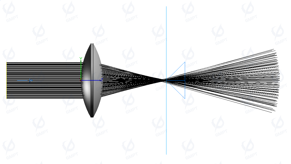
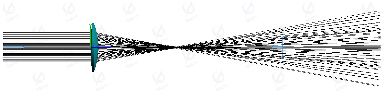
When light rays parallel to the optical axis pass through a convex lens, they converge toward the focal point due to the lens's geometry and refractive properties. However, due to variations in how the lens’s center and edges converge light, a phenomenon known as spherical aberration can occur. This results in light rays not converging at a single point but rather forming a diffuse spot.
3.2 Concave Lens
3.2.1 Principle Introduction
A concave lens is thinner in the center and thicker at the edges, with both surfaces curving inward. When light rays parallel to the optical axis enter a concave lens, the lens’s geometry and refractive properties cause the rays to diverge outward. Some rays also reflect back toward a virtual focal point located on the same side as the light source.
3.2.2 Simulation Setup
Optical Component:
| Components | Diameter | Thickness | Lens Front Surface | Lens Rear Surface | (x, y, z, α, β, γ) | Material | Optical Properties | ||
|---|---|---|---|---|---|---|---|---|---|
| Radius | Concavity | Radius | Concavity | ||||||
| Concave_Lens | 100 | 20 | 200 | Concave | 200 | Concave | (0,0,0,0,0,0) | BK7 | 100% Transmittance |
Source and Receiver:
| Components | L | W | (x, y, z, α, β, γ) | Additional Settings |
|---|---|---|---|---|
| SurfaceSource | 50 | 50 | (0,0,-100,0,0,0) | Angular Distribution: Uniform Angle From:0 Angle to:0 Spectrum: Wavelength: 550 Weight: 1 |
| PlaneReceiver | 200 | 200 | (0,0,80,0,0,0) | --- |
3.2.3 Result Analysis
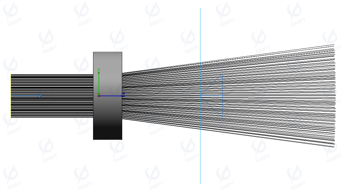
When rays parallel to the optical axis pass through a concave lens, they diverge outward. This behavior is illustrated in the ray preview below.
3.3 Achromatic (Glued) Lens
3.3.1 Principle Introduction
As we know, in optical imaging systems, single lenses produce chromatic dispersion due to the varying refraction caused by different wavelengths of incident light. To address this dispersion issue in lens imaging, achromatic doublet lenses were developed. A doublet lens is a compound lens made by combining two materials with different dispersive properties. The basic principle behind this is to use the differing dispersion characteristics of the two types of glass to counteract each other, thereby achieving chromatic aberration correction.
According to the dispersive property of glass materials, it is defined as:
It follows that as decreases, dispersion becomes stronger; when exceeds 50, the material is classified as low-dispersion glass, typically referred to as crown glass. Conversely, when is below 50, the glass is termed high-dispersion glass, commonly known as flint glass.
Achromatic doublet lenses are created by bonding a concave flint glass lens, with strong dispersion, to a convex crown glass lens, which has low dispersion. When these two lenses are tightly combined, the differential dispersion rates of the two materials can compensate each other, allowing correction of chromatic aberrations for specific wavelengths. By optimizing the curvature between the two glasses, the chromatic aberration generated by the concave lens is counterbalanced by the convex lens.
The objective of a doublet lens is to align the focal lengths of the longest and shortest wavelengths, while the intermediate wavelength (specifically the yellow wavelength, 587.56 nm) cannot be fully adjusted, resulting in residual chromatic aberration. This is a limitation present in all telescopes today. Although residual chromatic aberration cannot be entirely eliminated, this configuration allows different wavelengths to converge more accurately at a single focal point.
3.3.2 Simulation Settings
Optical Components:
| Components | Diameter | Thickness | LensFrontSurface | LensRearSurface | (x,y,z,α,β,γ) | Material | Optical Properties | ||
|---|---|---|---|---|---|---|---|---|---|
| Radius | Concavity | Radius | Concavity | ||||||
| BOC_Glued Lens_Convex | 112 | 18 | 480 | Convex | 154 | Convex | (0,0,0,0,0,0) | N-PSK57 | 100% Transmittance |
| BOC_Glued Lens_Concave | 112 | 5 | 154 | Concave | 325 | Concave | (0,0,18,0,0,0) | LAFN7 | 100% Transmittance |
Light Source and Receiver:
| Components | L | W | (x,y,z,α,β,γ) | Additional Settings |
|---|---|---|---|---|
| SurfaceSource | 70 | 70 | (0,0,-200,0,0,0) | Angular Distribution: Uniform Angle From:0 Angle to:0 Spectrum:Continuous Spectrum BlackBody Temperature Temperature:6500 Min Wavelength:380 Max Wavelength:780 Count:100 |
| PlaneReceiver | 200 | 200 | (0,0,415,0,0,0) | --- |
3.3.3 Result Analysis
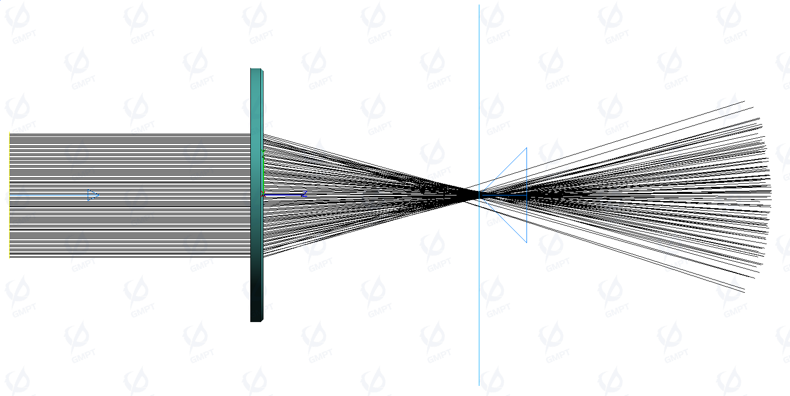
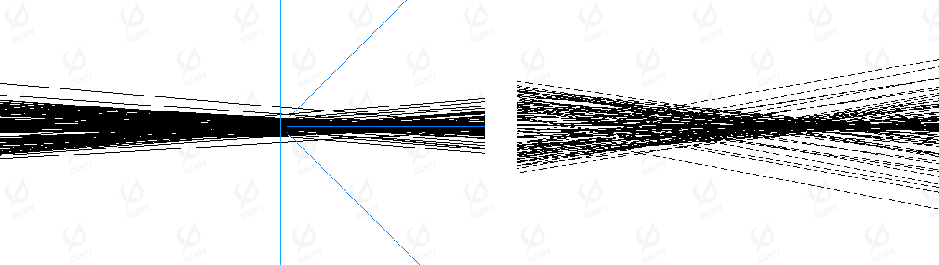
The light rays parallel to the optical axis enter the glued lens assembly and single convex lens as shown in the preview below. The focal lengths of the two setups differ noticeably; within the glued lens, the positive lens's refractive index is present, although its value is slightly lower than that of a single convex lens. This results in the glued lens having a further focal point.
Comparing the focusing details of the glued lens and single convex lens, the chromatic aberration produced by the convex lens in the glued lens is offset by the concave lens, resulting in a more focused beam, as shown on the left. In contrast, the light beam in the single convex lens remains dispersed at the focal point due to chromatic aberration, as seen on the right.
3.4 Fresnel Lens
3.4.1 Principle Introduction
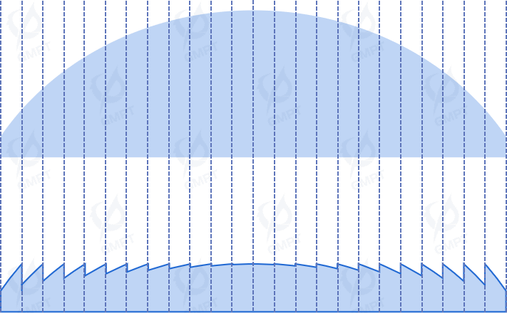
A Fresnel lens minimizes lens volume by removing as much optical material as possible while retaining the surface curvature responsible for refraction. This creates a lens with similar optical properties but with reduced thickness. A cross-section of a Fresnel lens reveals a series of jagged grooves, with an elliptical arc in the central region. Each groove has a unique angle, but collectively they focus light to a central point, forming the lens’s focal point. The principle of the Fresnel lens involves concentric grooves on the lens surface, which alter light phase and amplitude through variable depth and width. When light passes through the Fresnel lens, it undergoes diffraction due to the groove structure, focusing or dispersing light to control its path. Lighter and thinner than traditional lenses, Fresnel lenses are ideal for use in optical devices and communication systems.
3.4.2 Simulation Settings
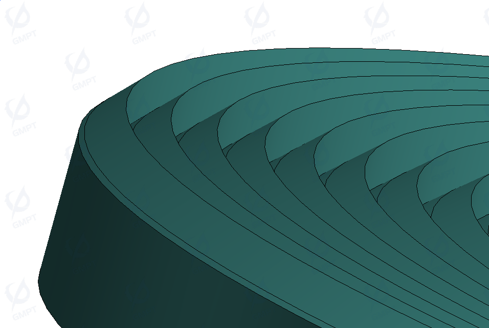
In this case, the Fresnel lens was constructed using a structural modeling software and imported in .STEP format.
Optical Components:
| Components | (x,y,z,α,β,γ) | Material(n,V,L) | Optical Properties |
|---|---|---|---|
| BOC_Frensh Lens | (0,0,0,180,0,0) | (1.4936,0.99986,10) | Ray Treatment: Transmitted and Reflected Transmitted only Ray Split Method:Power Ratio Power Threshold:Yes |
Light Source and Receiver:
| Components | L | W | (x,y,z,α,β,γ) | Additional Settings |
|---|---|---|---|---|
| PointSource | --- | --- | (0,0,-20,-,-,-) | Angular Distribution: Uniform Angle From:0 Angle to: PointSource:20 SurfaceSource:0 Spectrum:Continuous Spectrum BlackBody Temperature Temperature:6500 Min Wavelength:380 Max Wavelength:780 Count:100 |
| SurfaceSource | 10 | 10 | (0,0,-20,0,0,0) | |
| PlaneReceiver | 30 | 30 | (0,0,17,0,0,0) | --- |
3.4.3 Result Analysis
For a clear observation of all light paths emitted from the source, the Fresnel lens’s optical properties were set to non-sequential mode for full ray tracing. In this mode, some rays reflect upon contact with the lens surface, resulting in slight losses. Non-sequential mode ray analysis allows for observing and analyzing stray light sources in complex optical systems.
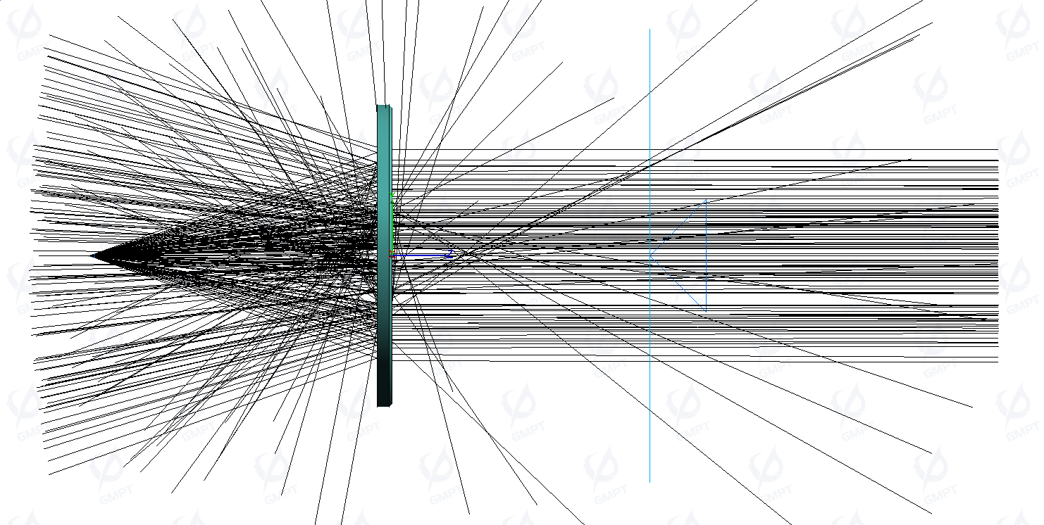
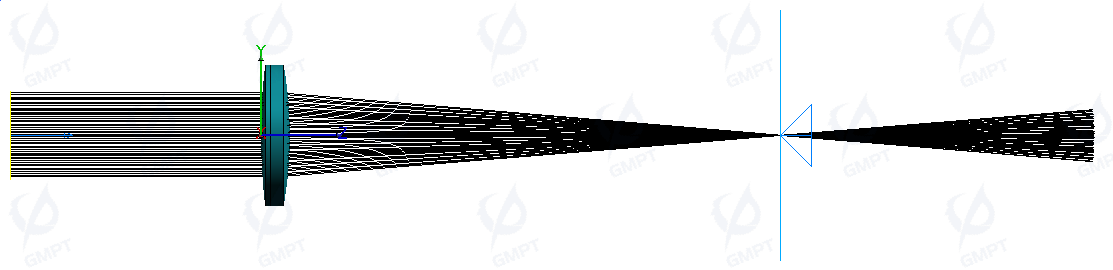
To analyze only the correct rays passing through the Fresnel lens while minimizing stray light interference, the optical properties can be adjusted to only transmit incident light. This mode, which approximates sequential tracing within non-sequential tracking, facilitates post-processing analysis. The ray preview after tracing is shown below:
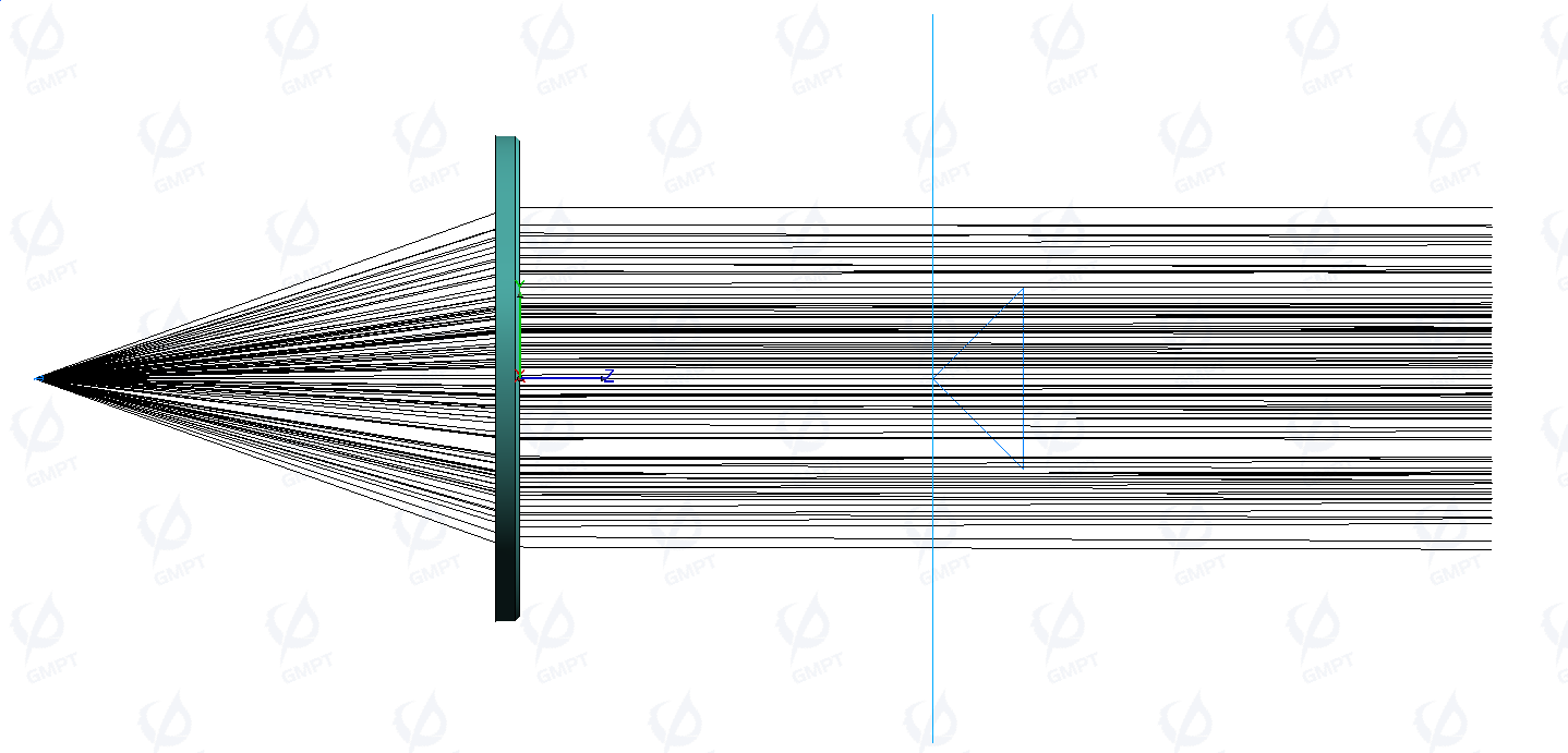
When light parallel to the optical axis enters the Fresnel lens, it converges along the optical axis, similar to a convex lens, but not to a single point, accompanied by chromatic dispersion.