Half-Ring Coupler (HalfRing)
GMPT, October 2024
1. Introduction
Directional couplers are common coupling devices used for splitting and combining light. They are composed of two adjacent waveguide structures. The half-ring coupler in this simulation is a directional coupler consisting of one straight waveguide and one half-ring structure. It has various applications in photonic integrated circuits, including:
- Light signal transmission: Guiding light signals from one waveguide to another for signal transfer.
- Optical path selection: Switching optical paths between different waveguides to achieve path selection.
- Light signal splitting: Dividing the incident light into multiple channels, enabling distributed sensing, multi-channel communication, etc.
- Light signal coupling: Coupling light signals from multiple waveguides into a single waveguide for multi-channel integration.
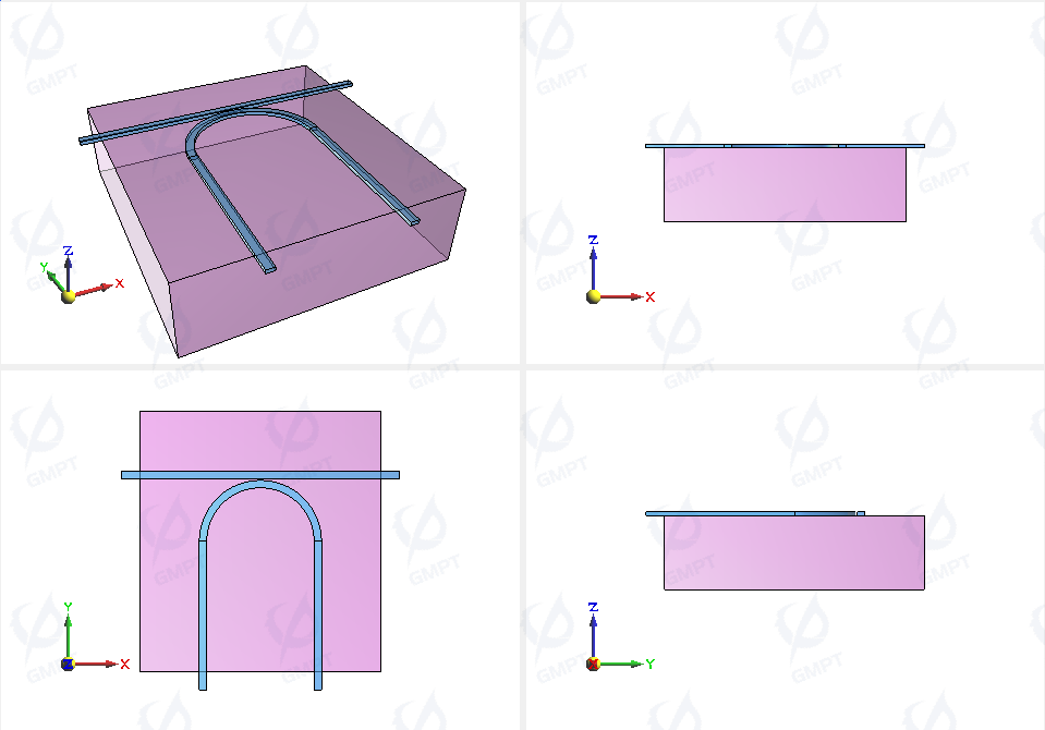
Structure of the half-ring coupler:
2. Working Principle
The refractive index distribution in a waveguide determines the propagation characteristics of different modes. When light propagates from one waveguide to an adjacent waveguide, refractive index differences cause light coupling. This phenomenon is explained by Coupled Mode Theory (CMT). Directional couplers utilize mode theory and coupled mode theory to achieve optical field coupling. By adjusting parameters such as the distance, shape, and refractive index of the two waveguides, coupling efficiency can be controlled, enabling directional coupling of light.
3. Device Structural Parameters
In this simulation, the half-ring resonator consists of a semi-ring-shaped waveguide and a straight waveguide placed on a silicon dioxide substrate. The structural parameters are as follows:
| Structural Parameter | Length |
|---|---|
| Outer diameter of ring waveguide (r1) | 3.3 μm |
| Inner diameter of ring waveguide (r2) | 2.9 μm |
| Straight waveguide width (Sy) | 0.4 μm |
| Distance between waveguides (d) | 0.1 μm |
| Waveguide thickness (thickness) | 0.18 μm |
In this simulation, a 1.5-1.6 μm light source is injected into the half-ring resonator and coupled at specific frequencies to the half-ring directional coupler. The transmission characteristics at each port are observed.
4. Simulation Results
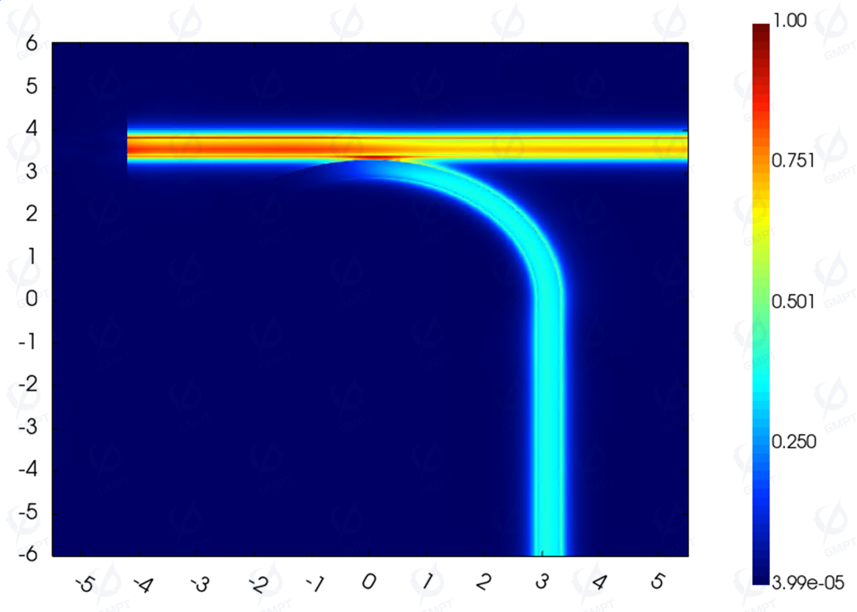
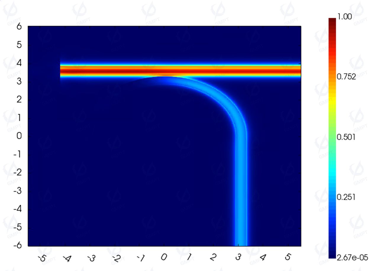
Optical field propagation distribution (wavelengths of 1.5 μm and 1.6 μm):
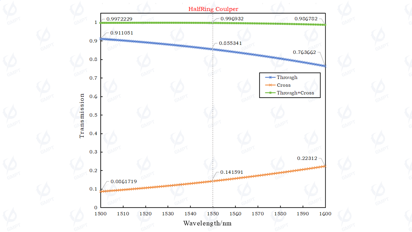
Transmission curves at Through and Cross ports:
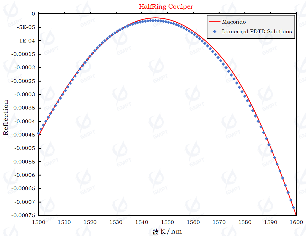
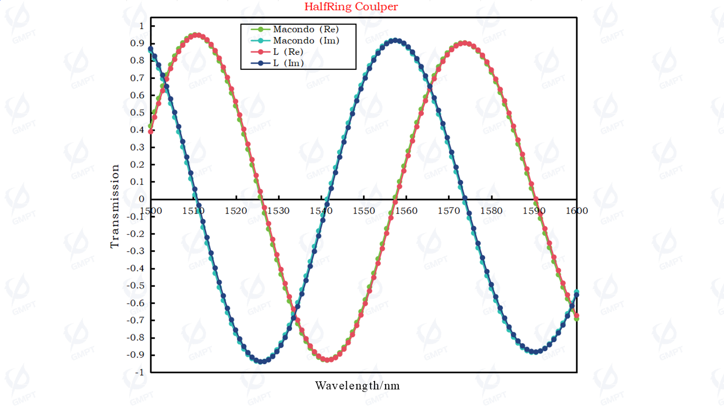
Comparison of Through port S-parameters with benchmark software:
Comparison of back reflection spectrum with benchmark software: