Polarization Splitter-Rotator (PSR)
GMPT, October 2024
1. Introduction
The Polarization Splitter-Rotator (PSR) is a photonic integrated device composed of an adiabatic taper, an asymmetric directional coupler (ADC), and a multimode interference (MMI) mode filter. The adiabatic taper enables effective mode conversion from the launched TM0 mode in a wide waveguide to the TE1 mode. It is then coupled to the TE0 mode of a narrow waveguide via the ADC. Meanwhile, the launched TE0 mode undergoes no direct mode conversion and is transmitted through the port. The MMI mode filter cascades at the through port to filter out residual power from the TE1 mode, significantly improving the PSR extinction ratio.
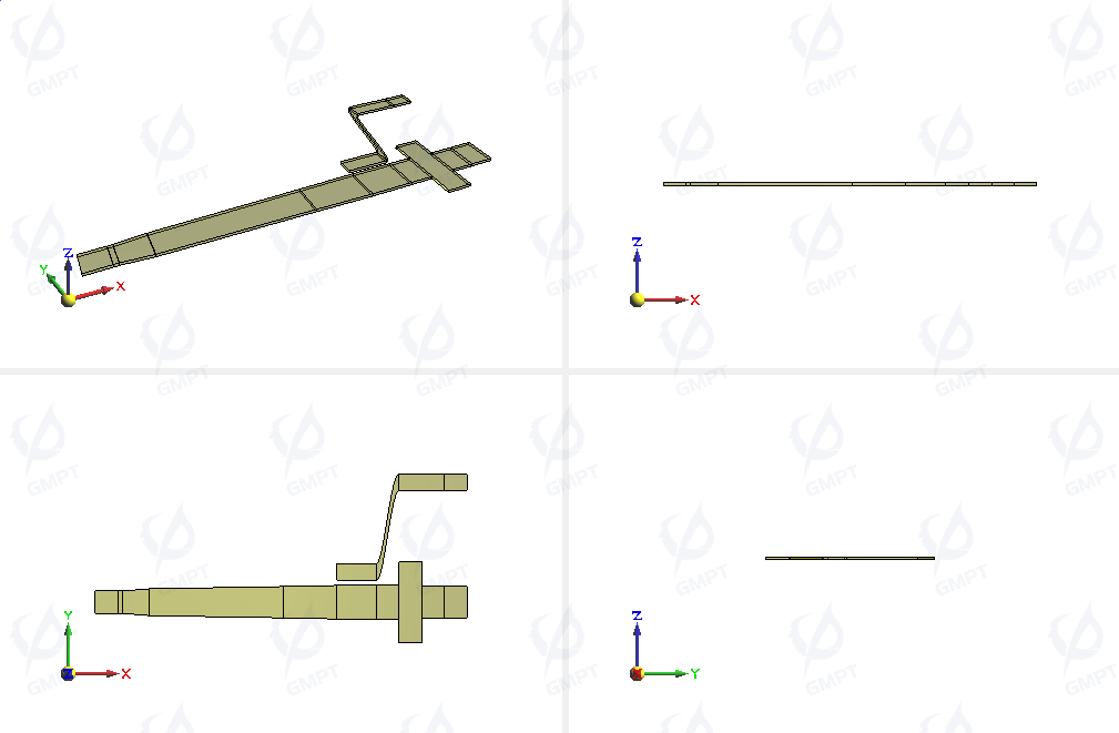
Polarization splitter-rotator device structure (not to scale):
2. Working Principle
When polarized light passes through the adiabatic tapered waveguide, the wide waveguide converts the launched TM0 mode to an effective TE1 mode. The TE1 mode is then coupled to the narrow waveguide’s TE0 mode via the ADC. Meanwhile, the launched TE0 mode undergoes no direct mode conversion and is transmitted through the port. The MMI mode filter cascades at the through port, filtering out residual TE1 mode power and improving the PSR extinction ratio.
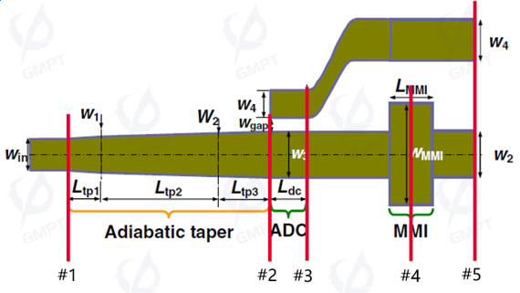
Device schematic:
3. Simulation Structure
The PSR design starts with a straight input port of width , followed by an adiabatic taper waveguide of length (composed of multiple taper segments). It then connects to an ADC of length , with widths and . This is followed by an MMI filter structure with length and width . The output port of the straight section has a width . The gap between the bent and straight ADC sections is , with the bent section's output port width . The PSR structure is placed on a silicon substrate thick (top surface at ).
The device structure used in this simulation is based on [1]. The total PSR length is , and the fabricated PSR achieves an extinction ratio of over a broadband range of –.
4. Simulation Results
In this simulation, monitors were placed at all PSR ports to observe parameters and transmission spectra under different mode excitations.
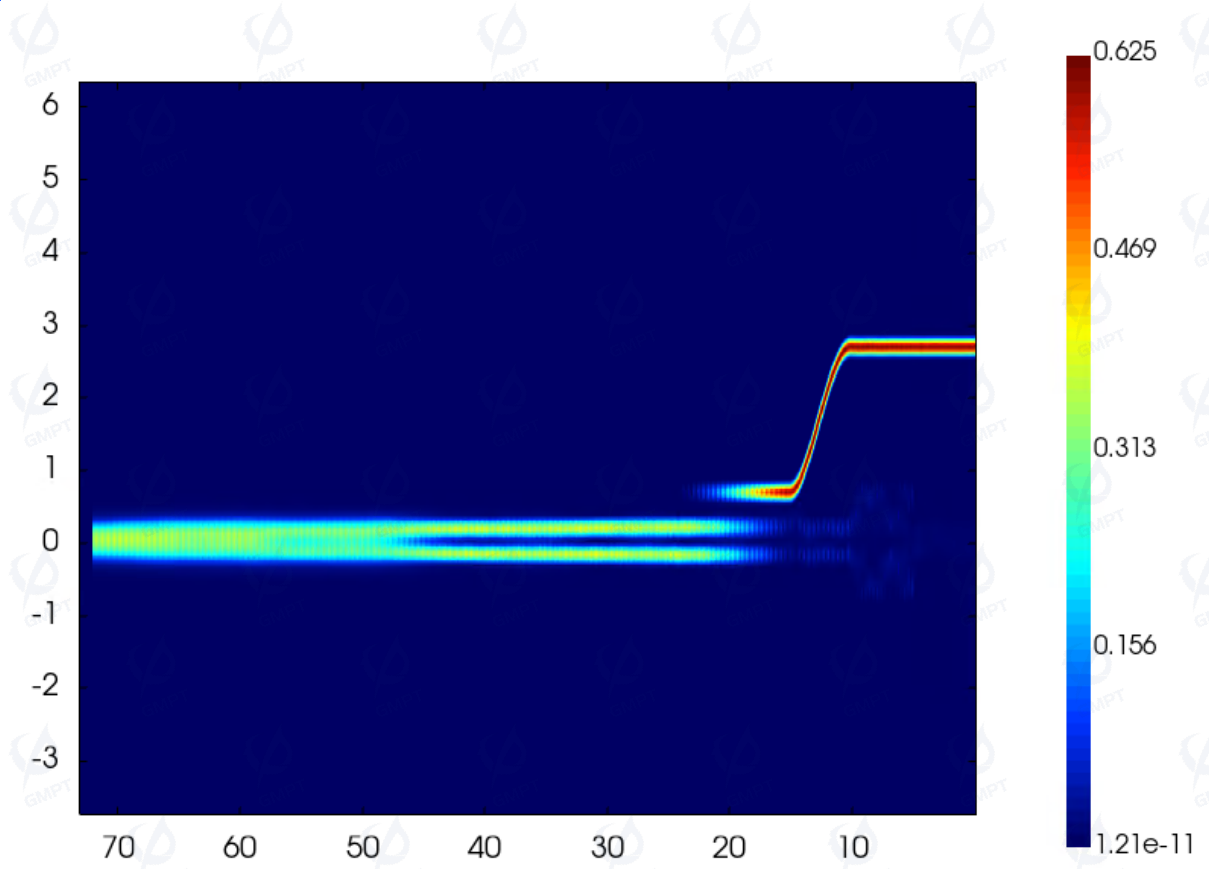
- TE0 mode source excitation at the straight input port. Field distribution, parameters, and transmission spectra were monitored at the ADC output port in TE0 mode.
TE0 mode field distribution:
TE0 mode excitation, parameters at the Through_Port and Cross_Port for TE0 mode output:
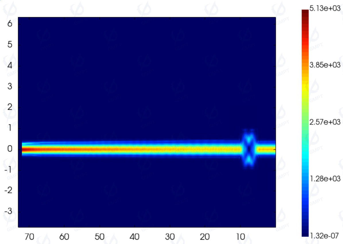
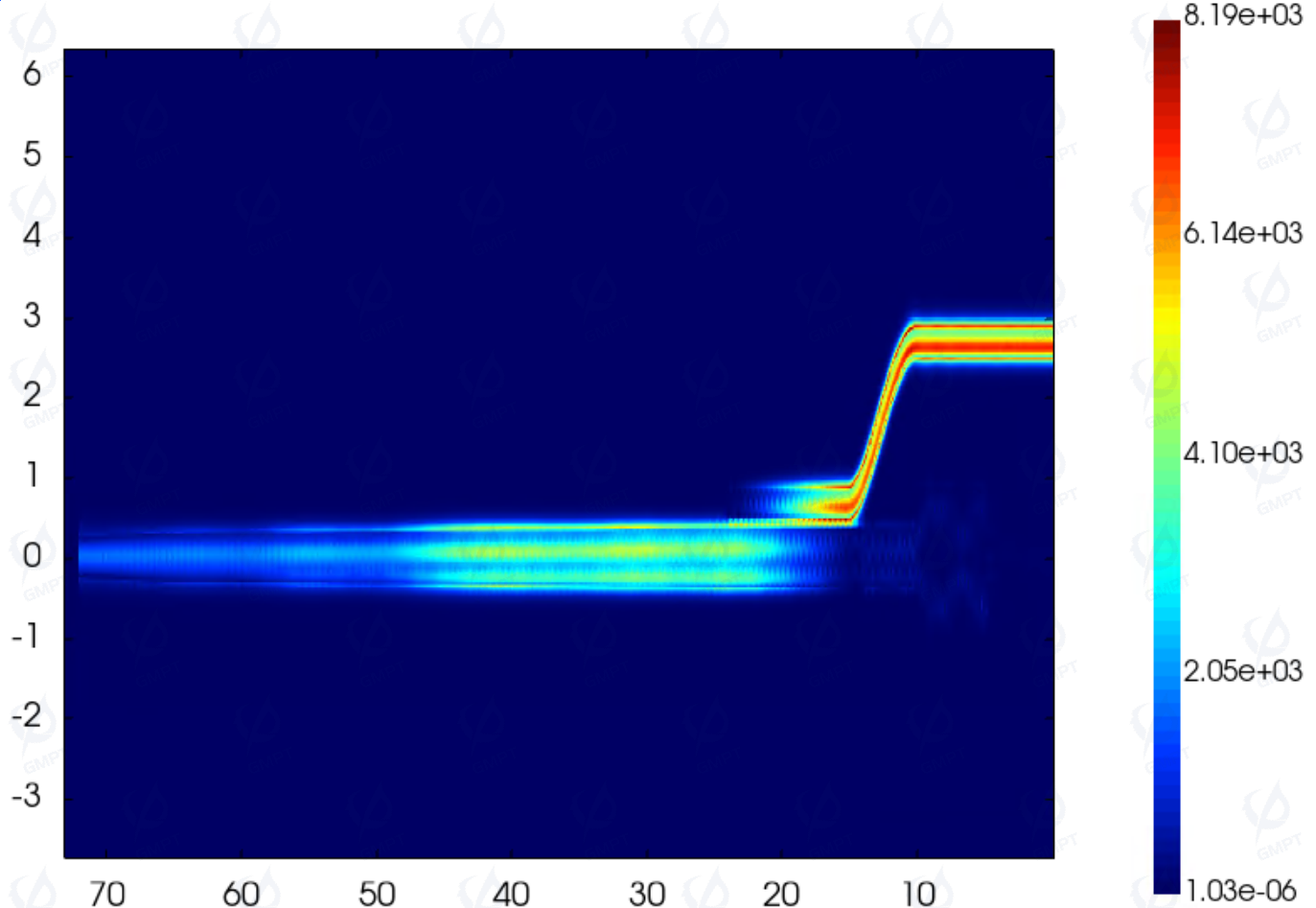
- TM0 mode source excitation at the straight input port. Field distribution, parameters, and transmission spectra were monitored at the ADC output port in TE1 mode.
TM0 mode field distribution:
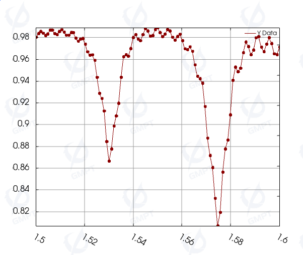
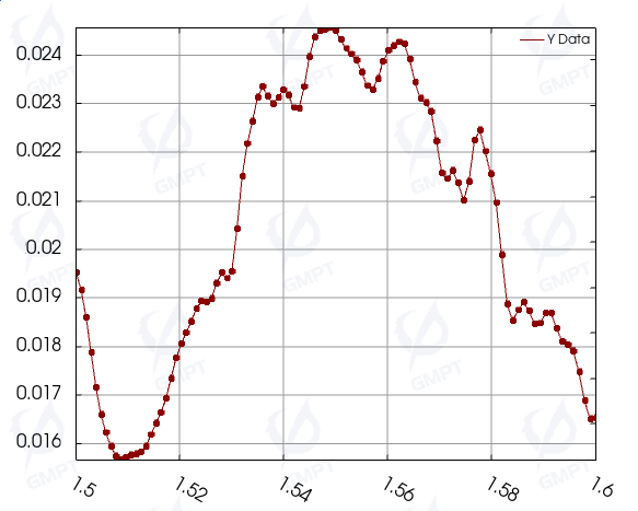
Transmission characteristics at output ports under different mode excitations:
| Incident Mode | Port | Transmission Rate |
|---|---|---|
| TE0 | Through_Port | 0.97558 |
| TE0 | Cross_Port | 0.00094854 |
| TM0 | Through_Port | 0.016925 |
| TM0 | Cross_Port | 0.89184 |
TM0 mode polarization conversion and coupling:
References
[1] Daoxin Dai and Hao Wu. Realization of a compact polarization splitter-rotator on silicon. Opt. Lett. 41, 2346–2349 (2016)