Micro-Ring Resonator (MRR)
GMPT, October 2024
1. Introduction
Micro-ring resonators are optical devices on a micro- to nanoscale, offering precise optical control. They are widely used in optical chips, optical communication, and sensing technologies. Their fundamental working principle involves guiding light waves into a small ring-shaped waveguide to generate resonance at specific wavelengths.
1.1 Working Principle
The core principle of a micro-ring resonator is based on the interference of light waves due to multiple reflections. When light of a specific wavelength is introduced into the micro-ring from the input waveguide, it undergoes multiple round trips in the ring, accumulating phase. If the accumulated phase equals an integer multiple of the wavelength, the light resonates within the ring, significantly increasing its intensity. This resonance wavelength is determined by the size and optical properties of the micro-ring.
1.2 Optical Control
The resonance wavelength of a micro-ring resonator can be controlled by tuning the geometry (e.g., radius) or the refractive index of the ring. This makes micro-ring resonators a versatile optical filter, capable of selecting specific wavelength ranges or dynamically adjusting resonance wavelengths in real time.
1.3 Applications
Micro-ring resonators have diverse applications, including but not limited to:
- Optical communication: Used in optical switches, filters, and wavelength division multiplexers for high-speed data transmission and optimized network connections.
- Sensing technology: Applied in optical sensors such as mechanical, biological, and chemical sensors to detect environmental changes, biomolecules, or chemical components.
- Optical chips: Serving as key components in integrated optical chips to build miniature photonic systems like optical oscillators and modulators.
- Quantum optics: Used for single-photon sources and quantum information processing, supporting quantum computing and communication fields.
1.4 Tuning Mechanisms
The resonance wavelength of a micro-ring resonator can be tuned through various mechanisms, such as thermo-optic effects, electro-optic effects, all-optical effects, and mechanical strain. These tuning methods enable rapid and precise wavelength adjustments for different applications.
2. Basic Principles of Micro-Ring Resonators
The simplest micro-ring resonator consists of a straight waveguide and a ring-shaped waveguide, as shown below:
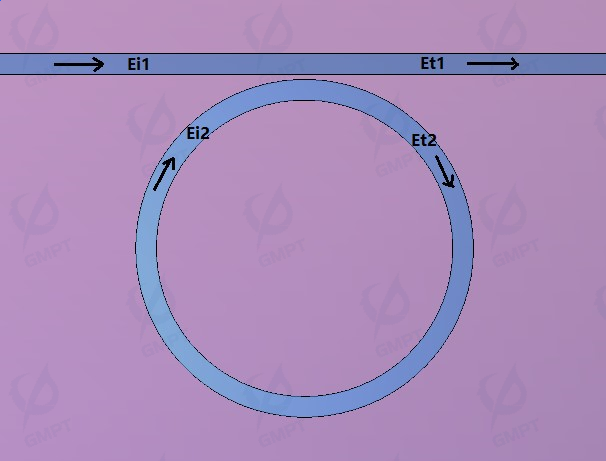
When light enters from one end of the straight waveguide, part of it couples into the ring waveguide due to the coupling effect as it passes through the adjacent region. Upon returning to the coupling region after propagating through the ring, the relationship between the ring circumference and the wavelength leads to two possible scenarios:
If the ring circumference is an integer multiple of the wavelength, constructive interference occurs, enhancing energy within the ring. This is known as the resonance state.
If the ring circumference is not an integer multiple of the wavelength, a non-resonant state occurs.
The relationship between the input and output light fields is expressed by the transfer matrix as follows:
Here, represents the coupling coefficient between the straight waveguide and the ring waveguide, and denotes the transmission coefficient. Assuming lossless coupling, the following relationship holds:
The transmission coefficient is defined as the ratio of the output power at the straight waveguide to the input power:
In this equation,αis the attenuation factor within the ring waveguide(α=1implies zero loss),θis the phase shift after one round trip around the ring.
When used as a filter, neglecting loss, the transmission coefficient is approximately 1 at non-resonant frequencies and nearly 0 at resonance. The transmission spectrum exhibits a comb-like structure, with the frequency spacing between peaks referred to as the Free Spectral Range (FSR).
3. Key Performance Metrics of Micro-Ring Resonators
3.1 Free Spectral Range (FSR)
When the micro-ring radius is fixed, the FSR for adjacent resonance peaks is given by:
where ngs the group refractive index and is the circumference of the ring waveguide.
3.2 Quality Factor (Q)
The quality factor () is defined as the ratio of the resonance wavelength to the full width at half maximum (FWHM) of the resonance peak. A higher value indicates better wavelength selectivity and steeper output peaks, thus enhancing device sensitivity:
where λ3dBis the bandwidth at -3 dB, calculated as:
3.3 Finesse (F)
The finesse () is defined as the ratio of the FSR to the 3 dB bandwidth:
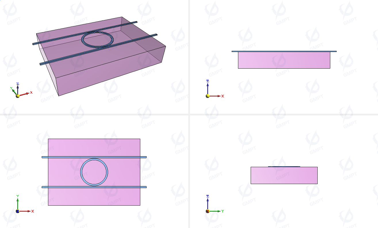
4. Device Structural Parameters
The outer diameter of the ring waveguide () is 3.3 μm, and the outer radius () is 2.9 μm. The width of the two parallel straight waveguides () is 0.4 μm, the distance between the ring and the waveguides () is 0.1 μm, and the thickness of the micro-ring resonator is 0.18 μm. It is placed on a 4 μm-thick silicon substrate (top surface at μm).
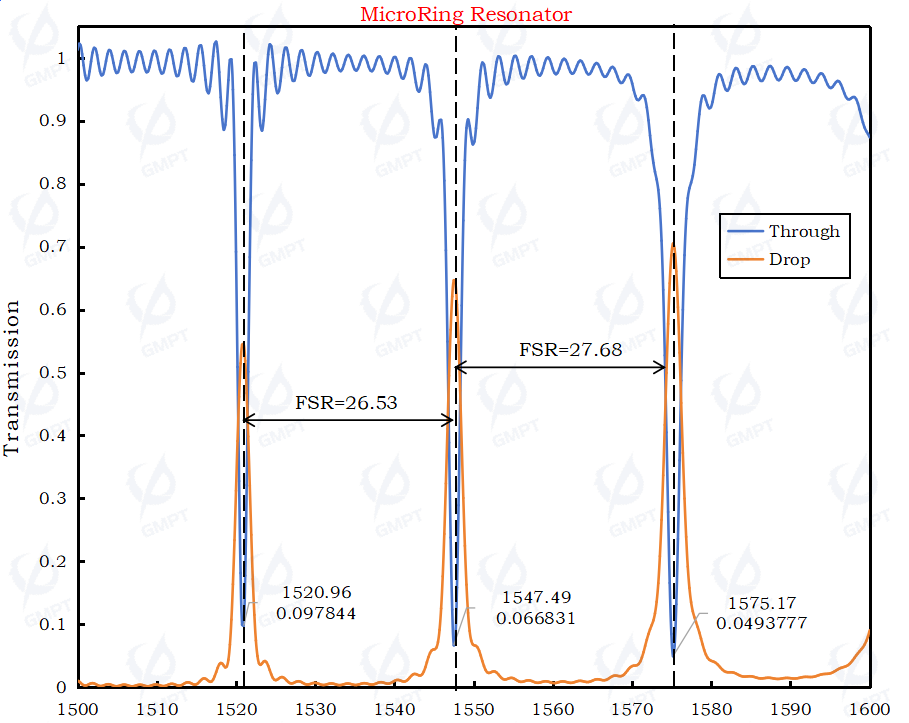
5. Simulation Results
Transmission spectra at the Through and Drop ports of the micro-ring resonator:
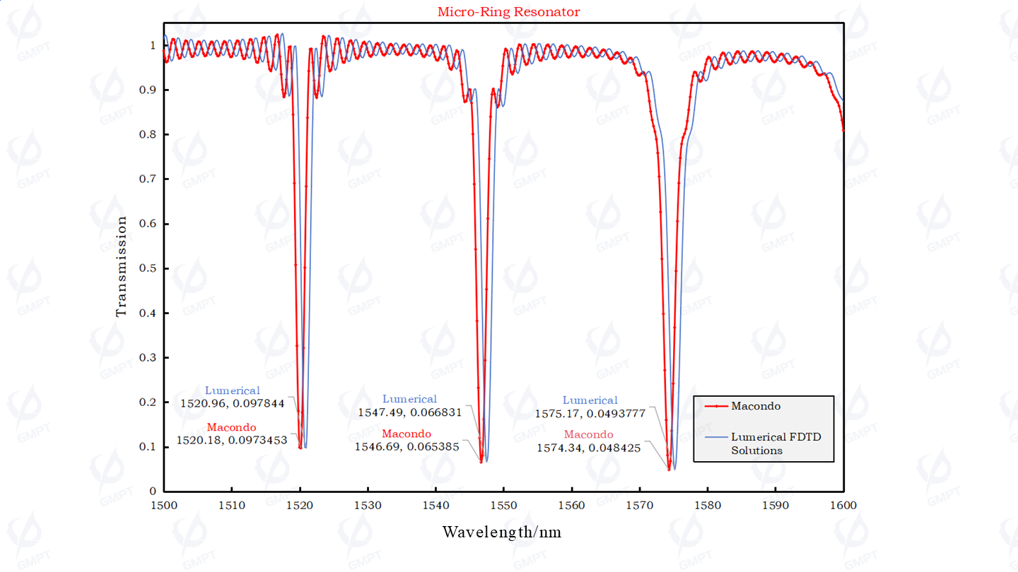
Macondo's Comparison with Benchmark Software
Comparison of MRR Through Port Transmission spectra: The difference in resonance wavelengths is approximately 0.8 nm, and the amplitude difference is about 0.001 at the resonance peak.
Comparison of Through port transmission spectra:
Comparison of the real and imaginary parts of the Through port S-parameters:
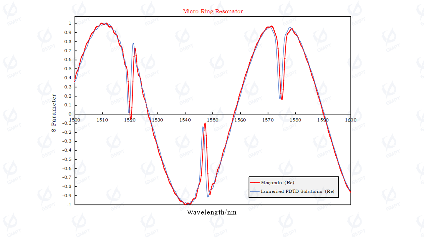
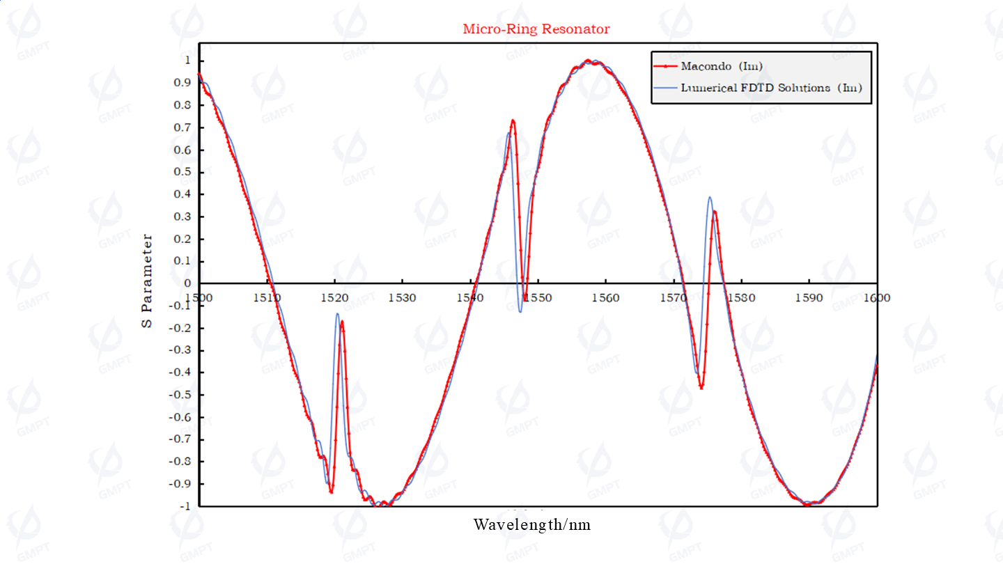
Thus, the FDTD3D solver in the Macondo software meets the precision requirements for critical device simulation metrics, providing tool support for silicon photonics device design.